
The sequencer is pretty much all of the digital control and I/O. There are a lot of parts but not many kinds of parts (70 10K resistors, 40 LEDs, 32 buttons, etc.)
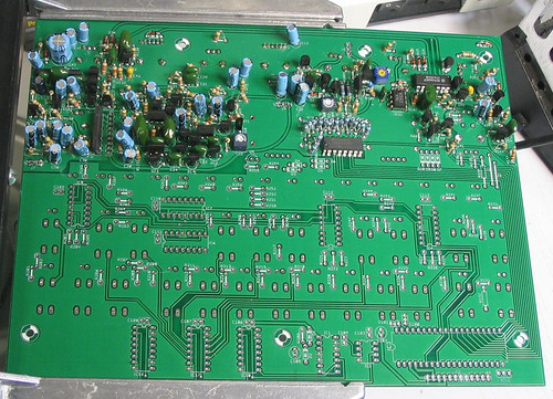
Before, bottom of mainboard
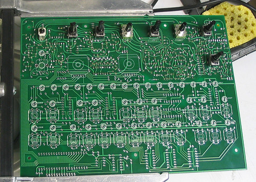
Before, top of mainboard
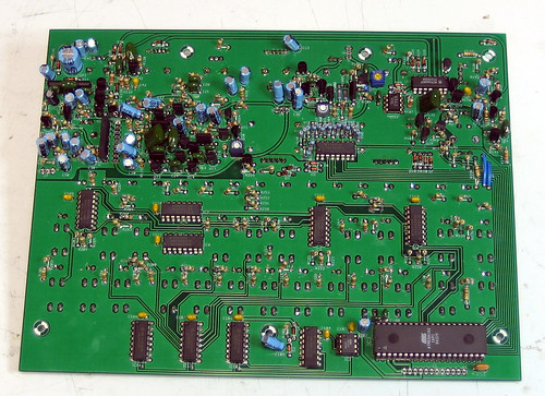
After, bottom of mainboard
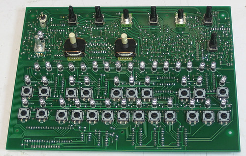
After, top of mainboard
If you want to use non-standard LEDs (the standard ones are rounded bright red) then you probably want to change the resistor values. See this post on the forum for the resistor and corresponding LED list (copied below). If you use the flat LEDs you'll want to replace each of those with a 1K resistor instead of a 10K resistor.
LED-RESISTOR:
1-234
2-237
3-241
4-242
5-243
6-244
7-250
8-251
9-252
10-253
11-256
12-260
13-261
14-262
15-266
16-267
17-268
18-238
19-239
20-245
21-246
22-248
23-249
24-258
25-265
26-264
27-203
28-229
29-228
30-227
31-223
32-222
33-221
34-217
35-215
36-213
37-211
38-208
39-205
40-204
The LEDs use standoffs, dont worry about which way the standoffs go, they're just pieces of plastic.
If you are using the standard LEDs, they're not so bad to line up, so you can use this technique:

To get the LEDs seated best, use something like a screwdriver to kink the leads (twist firmly between both leads) while pressing down on the LED into the board.
If you have the flat LEDs, you cant use the above technique: it will end in tears. The best trick I've got so far is to put the LEDs in the proper locations, then attach the top cover to the main PCB using the standoffs and top half of the enclosure. Basically you want to make sure the LEDs are flush when you're done.
Hold the PCB upside down, so you can jiggle each LED till they slide into the holes of the cover. Now they are lined up.
Next, for each LED, while its though the hole in the panel, solder one leg. Hold the tip of the soldering iron to the soldered leg and with your free hand, push the LED up through the panel hole all the way until its flush. Release the iron from the solder. Wait 3 seconds until the solder is 'set'. Now the LED is tacked in the proper position. Solder the other leg. Clip the LEDs. Repeat 39 more times!
Make sure you dont confuse the two types of serial/parallel converter chips. Also, put in the LEDs correctly or they wont light up: the flat side of the LED goes with the flat side of the picture
The EEPROM and microcontroller are socketed so dont solder them in directly.
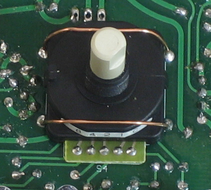
Before soldering the 5 pins of the rotary switches, they need to be secured & centered onto their silkscreen outline. Use bare wire to 'staple' the switches down. After soldering both ends (but before clipping off the excess), pull on the wire while heating one end at a time to make a snug fit.
Don't forget about the two wire jumpers, J1 and J2! They are seperate from the wires used to hold down the rotary switches above.
There are a lot of 10K resistors, LEDs and switches. It might be best to solder them in that order, although you should do whichever is best for your soldering iron and setup. Basically just think about what would be the easiest way to solder so that you dont melt the switches when soldering the other parts.
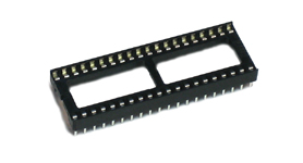 |
40-pin DIP socket | 1 | IC3* | |||||||
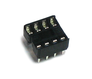 |
8-pin DIP socket | 1 | IC2* | |||||||
 |
Rotary encoder | 1 | S2 | |||||||
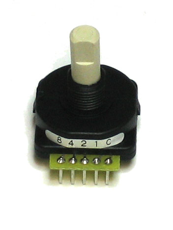 |
16 position rotary switch | 2 | S3, S4 | |||||||
| Solid gauge wire (jumpers) | 2 | J1, J2 | ||||||||
| Solid gauge wire (straps) | 2 | S3*, S4* | ||||||||
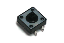 |
Tact switch | 23 | S5-S27 | |||||||
| Red 5mm LED | 40 | LED1-LED40 | ||||||||
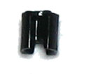 |
0.22" LED standoff | 40 | LED1*-LED40* | |||||||
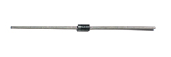 |
1N4148 | 10 | D1-D10 | |||||||
|
10K 5% resistor | 68 | R201-R234, R237-R270. | |||||||
|
220K 5% resistor | 2 | R235, R236 | |||||||
|
1MEG 5% resistor | 1 | R200 | |||||||
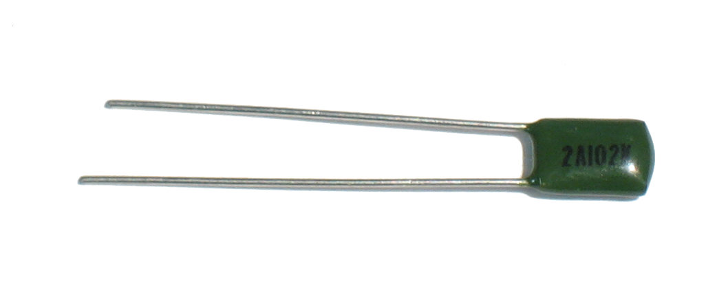 |
.001uF (2A102K) capacitor | 2 | C100, C101 | |||||||
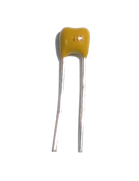 |
.1uF (104) ceramic | 10 | C103, C104, C106-C113 | |||||||
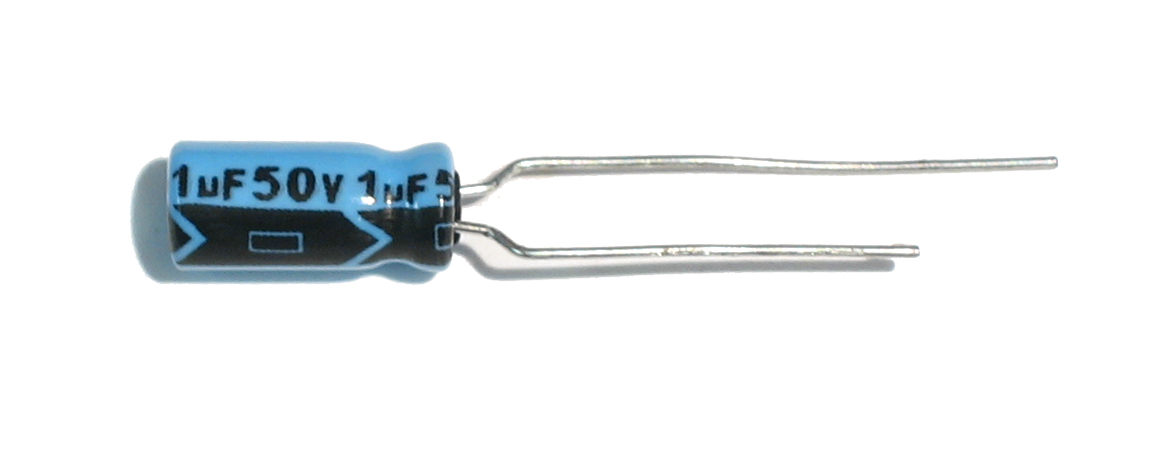 |
1uF electrolytic capacitor | 1 | C105 | |||||||
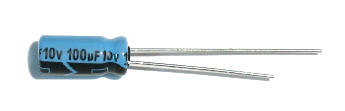 |
100uF 10V electrolytic capacitor | 1 | C102 | |||||||
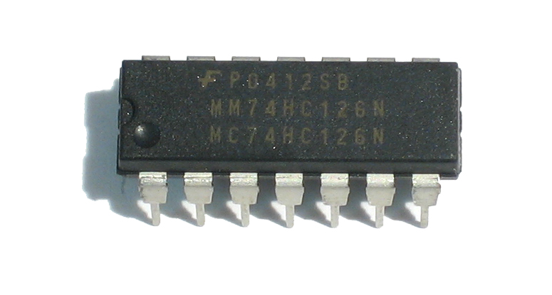 |
74AC126 | 1 | IC1 | |||||||
| 74AC165 | 3 | IC16-IC18 | ||||||||
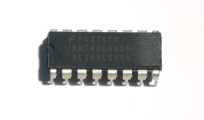 |
74AC595 | 5 | IC4-IC8 | |||||||
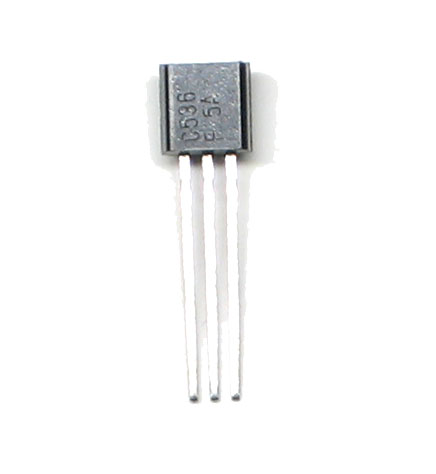 |
2SC536F, TO-92 NPN transistor | 1 | Q5 | |||||||
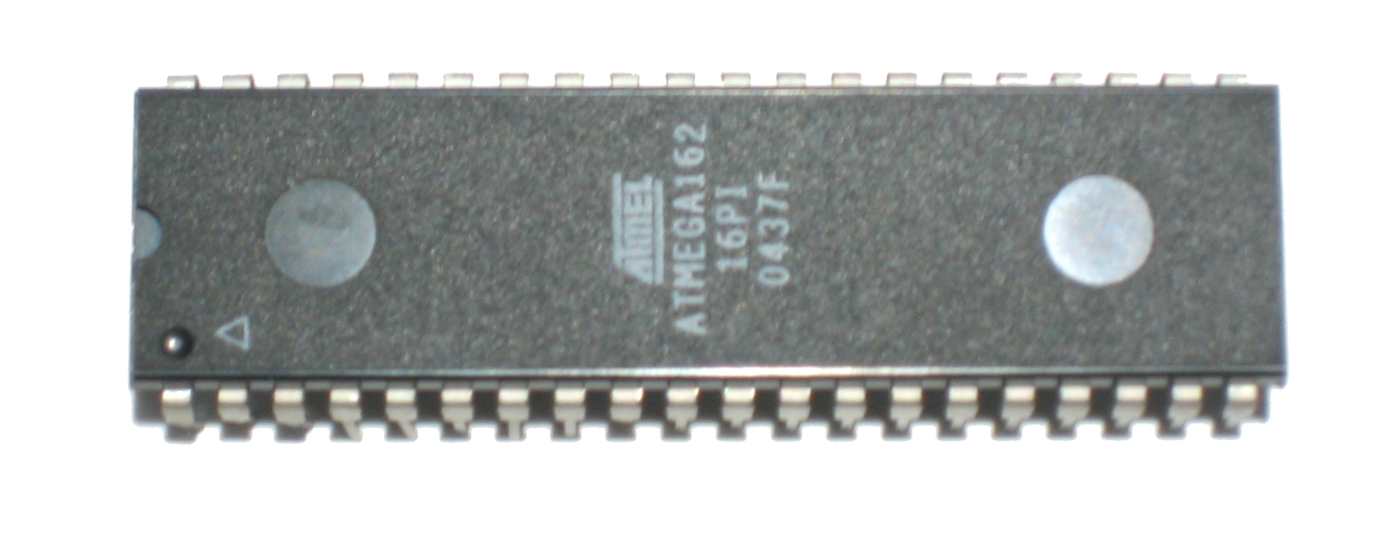 |
ATmega162 microcontroller | 1 | IC3 | |||||||
 |
25C33 or AT25320 32K EEPROM | 1 | IC2 | |||||||
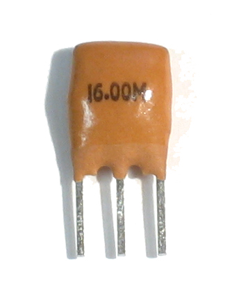 |
16MHz ceramic resonator | 1 | XTAL1 |

